


This should take overall.

This 3D Model consists of files in StereoLithography (.Stl) format that is optimized for 3D printing.
Before printing the files, we strongly recommend reading the PRINTING DETAILS section.
AT-M6 Walker 3D Printing Model comes in 4 versions for each 3D printer type (FFF/FDM, DLP/SLA). Files for each version are available for download after the purchase.
Detailed information about this 3D printing model is available in the DESCRIPTION section.

|
|||||
|---|---|---|---|---|---|
| File Name | File Size | Time / Filament | Object Size (x/y/z mm) |
||
|
1_head_FDM (repaired).stl |
35.76 MiB | 19 h 15 min 12 m | 66 x 79 x 79 | Download | |
|
2_head_roof_FDM (repaired ).stl |
1.56 MiB | 4 h 47 min 3 m | 51 x 34 x 76 | Download | |
|
3_head_gun_side_R_FDM (re paired).stl |
8.23 MiB | 48 min <1 m | 19 x 22 x 38 | Download | |
|
4_head_gun_side_L_FDM (re paired).stl |
8.23 MiB | 48 min <1 m | 19 x 22 x 38 | Download | |
|
5_head_gun_front_R_FDM (r epaired).stl |
0.68 MiB | 24 min <1 m | 7 x 14 x 37 | Download | |
|
6_head_gun_front_L_FDM (r epaired).stl |
0.67 MiB | 24 min <1 m | 7 x 14 x 37 | Download | |
|
7_windows_front_FDM (repa ired).stl |
0.00 MiB | 2 min <1 m | 23 x 4 x 1 | Download | |
|
8_windows_R_FDM (repaired ).stl |
0.00 MiB | 2 min <1 m | 6 x 21 x 1 | Download | |
|
9_windows_L_FDM (repaired ).stl |
0.00 MiB | 2 min <1 m | 6 x 21 x 1 | Download | |
|
10_neck_FDM (repaired).st l |
9.31 MiB | 8 h 5 min 5 m | 44 x 39 x 119 | Download | |
|
11_body_front_FDM (repair ed).stl |
28.71 MiB | 66 h 24 min 48 m | 107 x 162 x 86 | Download | |
|
12_body_center_FDM (repai red).stl |
20.00 MiB | 48 h 24 min 29 m | 99 x 161 x 99 | Download | |
|
13_body_back_FDM (repaire d).stl |
18.41 MiB | 36 h 55 min 23 m | 99 x 107 x 98 | Download | |
|
14_body_bot_1_FDM (repair ed).stl |
1.06 MiB | 6 h 8 min 3 m | 43 x 39 x 66 | Download | |
|
15_body_bot_2_FDM (repair ed).stl |
0.23 MiB | 3 h 48 min 2 m | 45 x 48 x 38 | Download | |
|
16_bot_pipes_FDM (repaire d).stl |
0.32 MiB | 20 min <1 m | 13 x 22 x 14 | Download | |
|
17_body_gun_FDM (repaired ).stl |
15.36 MiB | 3 h 15 min 2 m | 40 x 32 x 85 | Download | |
|
18_flap_R_FDM (repaired). stl |
0.06 MiB | 51 min <1 m | 8 x 38 x 34 | Download | |
|
19_flap_L_FDM (repaired). stl |
0.06 MiB | 52 min <1 m | 8 x 38 x 34 | Download | |
|
20_panel_top_R_FDM (repai red).stl |
0.03 MiB | 28 min <1 m | 18 x 39 x 10 | Download | |
|
21_panel_top_L_FDM (repai red).stl |
0.03 MiB | 28 min <1 m | 18 x 39 x 10 | Download | |
|
22_bridge_lid_FDM (repair ed).stl |
0.46 MiB | 1 h 42 min 1 m | 34 x 95 x 24 | Download | |
|
23_body_top_1_FDM (repair ed).stl |
7.97 MiB | 7 h 27 min 4 m | 65 x 89 x 27 | Download | |
|
24_body_top_2_FDM (repair ed).stl |
8.57 MiB | 8 h 52 min 5 m | 65 x 88 x 37 | Download | |
|
25_back_cell_1_FDM (repai red).stl |
2.19 MiB | 1 h 13 min 1 m | 27 x 27 x 22 | Download | |
|
26_back_cell_2_FDM (repai red).stl |
0.44 MiB | 49 min <1 m | 30 x 30 x 17 | Download | |
|
27_back_cell_3_FDM (repai red).stl |
2.19 MiB | 1 h 13 min 1 m | 27 x 27 x 22 | Download | |
|
28_front_leg_1_mount_R_FD M (repaired).stl |
0.30 MiB | 54 min 1 m | 73 x 20 x 7 | Download | |
|
29_front_leg_1_R_FDM (rep aired).stl |
1.46 MiB | 2 h 40 min 2 m | 80 x 57 x 25 | Download | |
|
30_front_leg_2_R_FDM (rep aired).stl |
2.81 MiB | 8 h 12 min 5 m | 21 x 53 x 108 | Download | |
|
31_front_leg_2_cap_R_FDM (repaired).stl |
0.44 MiB | 43 min 1 m | 15 x 36 x 15 | Download | |
|
32_front_shin_connector_R _FDM (repaired).stl |
0.52 MiB | 1 h 18 min 1 m | 14 x 35 x 59 | Download | |
|
33_front_shin_R_FDM (repa ired).stl |
8.31 MiB | 18 h 44 min 11 m | 52 x 67 x 140 | Download | |
|
34_front_foot_connector_R _FDM (repaired).stl |
0.47 MiB | 1 h 17 min 1 m | 15 x 29 x 52 | Download | |
|
35_front_foot_R_FDM (repa ired).stl |
4.64 MiB | 8 h 47 min 5 m | 69 x 76 x 53 | Download | |
|
36_front_leg_1_mount_L_FD M (repaired).stl |
0.30 MiB | 53 min 1 m | 73 x 20 x 7 | Download | |
|
37_front_leg_1_L_FDM (rep aired).stl |
1.46 MiB | 2 h 40 min 2 m | 80 x 57 x 25 | Download | |
|
38_front_leg_2_L_FDM (rep aired).stl |
2.80 MiB | 8 h 20 min 5 m | 21 x 53 x 108 | Download | |
|
39_front_leg_2_cap_L_FDM (repaired).stl |
0.44 MiB | 43 min 1 m | 15 x 36 x 15 | Download | |
|
40_front_shin_connector_L _FDM (repaired).stl |
0.52 MiB | 1 h 18 min 1 m | 14 x 35 x 59 | Download | |
|
41_front_shin_L_FDM (repa ired).stl |
8.31 MiB | 18 h 49 min 11 m | 52 x 67 x 140 | Download | |
|
42_front_foot_connector_L _FDM (repaired).stl |
0.48 MiB | 1 h 17 min 1 m | 15 x 29 x 52 | Download | |
|
43_front_foot_L_FDM (repa ired).stl |
4.64 MiB | 8 h 46 min 5 m | 69 x 76 x 53 | Download | |
|
44_back_leg_1_R_FDM (repa ired).stl |
4.85 MiB | 3 h 59 min 2 m | 43 x 102 x 40 | Download | |
|
45_back_leg_2_R_FDM (repa ired).stl |
2.34 MiB | 6 h 52 min 4 m | 19 x 44 x 116 | Download | |
|
46_back_leg_2_cap_R_FDM ( repaired).stl |
0.44 MiB | 21 min <1 m | 11 x 27 x 11 | Download | |
|
47_back_shin_connector_R_ FDM (repaired).stl |
0.50 MiB | 1 h 17 min 1 m | 13 x 33 x 61 | Download | |
|
49_back_shin_pipe_R_FDM ( repaired).stl |
0.15 MiB | 26 min <1 m | 9 x 53 x 17 | Download | |
|
50_back_shin_cap_R_FDM (r epaired).stl |
0.81 MiB | 1 h 60 min 1 m | 40 x 50 x 15 | Download | |
|
51_back_foot_connector_R_ FDM (repaired).stl |
1.04 MiB | 1 h 26 min 1 m | 59 x 34 x 12 | Download | |
|
52_back_foot_R_FDM (repai red).stl |
0.82 MiB | 6 h 3 min 3 m | 87 x 87 x 35 | Download | |
|
53_back_leg_1_L_FDM (repa ired).stl |
4.85 MiB | 3 h 59 min 2 m | 43 x 102 x 40 | Download | |
|
54_back_leg_2_L_FDM (repa ired).stl |
2.34 MiB | 6 h 57 min 4 m | 19 x 44 x 116 | Download | |
|
55_back_leg_2_cap_L_FDM ( repaired).stl |
0.44 MiB | 21 min <1 m | 11 x 27 x 11 | Download | |
|
56_back_shin_connector_L_ FDM (repaired).stl |
0.50 MiB | 1 h 17 min 1 m | 13 x 33 x 61 | Download | |
|
58_back_shin_pipe_L_FDM ( repaired).stl |
0.15 MiB | 25 min <1 m | 9 x 53 x 17 | Download | |
|
59_back_shin_cap_L_FDM (r epaired).stl |
0.81 MiB | 1 h 59 min 1 m | 40 x 50 x 15 | Download | |
|
60_back_foot_connector_L_ FDM (repaired).stl |
1.04 MiB | 1 h 27 min 1 m | 59 x 34 x 12 | Download | |
|
61_back_foot_L_FDM (repai red).stl |
0.47 MiB | 5 h 51 min 3 m | 87 x 87 x 35 | Download | |
|
62_Ge_lock_10H_x25_FDM (r epaired).stl |
0.03 MiB | 4 min <1 m | 10 x 18 x 2 | Download | |
|
48_back_shin_R_FDM (repai red).stl |
5.34 MiB | 7 h 31 min 4 m | 25 x 54 x 100 | Download | |
|
57_back_shin_L_FDM (repai red).stl |
5.31 MiB | 7 h 28 min 4 m | 25 x 54 x 100 | Download | |
|
Keychain (repaired).stl |
0.35 MiB | 23 min <1 m | 30 x 30 x 2 | Download | |
|
Tag (repaired).stl |
1.70 MiB | 1 h 16 min 1 m | 150 x 18 x 5 | Download | |
| ... | |||||
This should take overall.
ABOUT THIS 3D MODEL
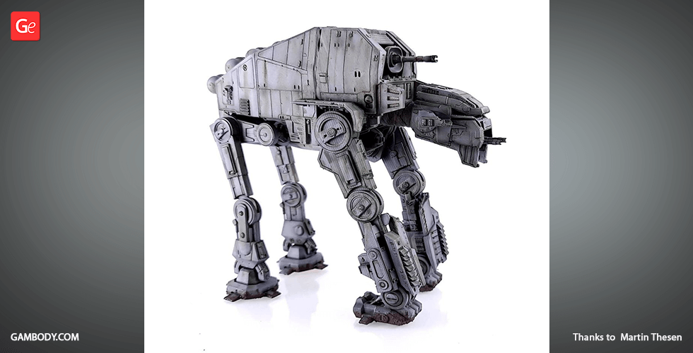
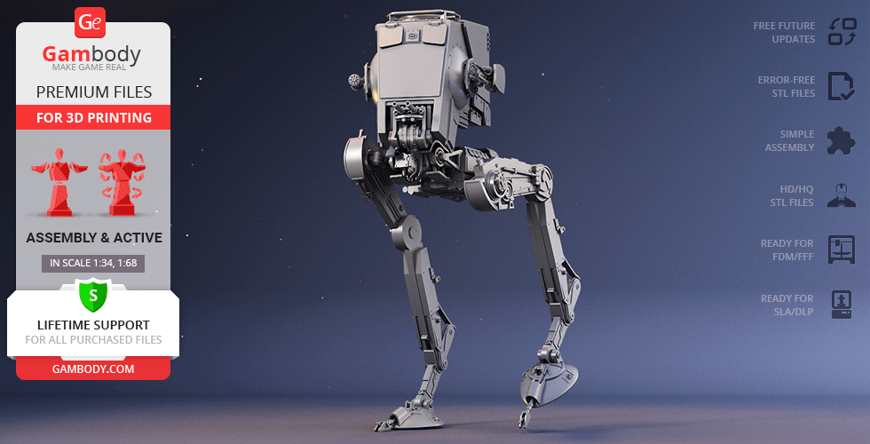
The massive and extremely intimidating walker AT-M6 instilled sheer terror into enemies of First Order in the course of Star Wars: The Last Jedi film. The All Terrain MegaCaliber Six was manufactured in the years following the end of the Galactic Civil War by Kuat-Entralla Drive Yards, the company that produced AT-M6’s predecessor AT-AT. At 40.87 meter long the Gorilla walker is actually almost twice the length of an AT-AT! It is also known to be coated in some of the most advanced armour in the Galaxy manufactured at secret facilities. And the reason why this walker had to be so large and powerful was both to hold that MegaCaliber Six turbolaser cannon and to make the heavy assault walker even more fearsome. The author of this huge 3D printing project spent 160 hours to create the model inspired by the AT-M6's most notable deployment during the Battle of Crait. The level of detail and attention to the functionality of the assembly parts will definitely impress you. Due to the model’s movability, one can even recreate the knuckle-dragging movement of AT-M6’s distinctive gorilla-like front feet! We are sure that any Star Wars fan will be delighted to enlarge the 3D printed collection with the walker that can do more damage than the orbital bombardment.
ADAPTATION FOR 3D PRINTING
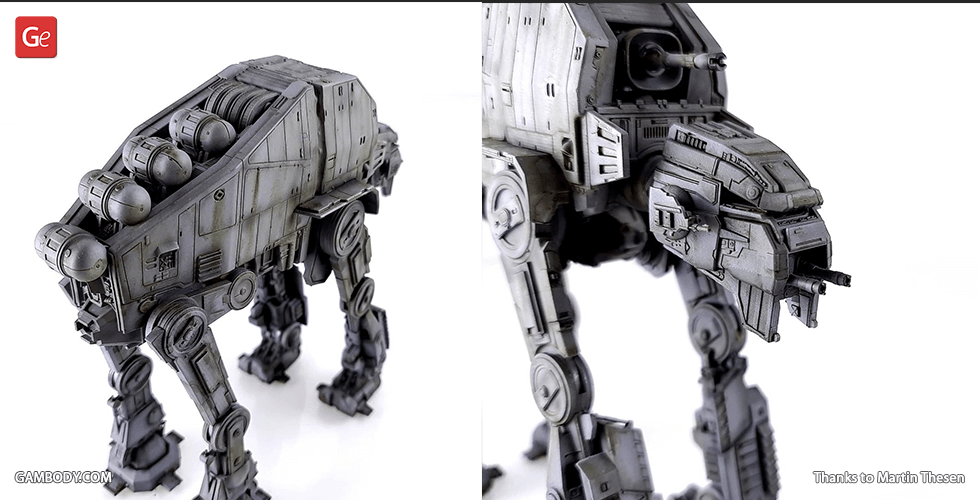
AT-M6 Walker model for 3D printing is an articulated assembly model and its moderation and adaptation for different types of 3D printers took Gambody team 80 hours in total. For you to receive the cleanest printing result possible and to minimise the amount of filament needed for generated support the First Order walker model was divided into many assembly parts, e.g. chin-mounted heavy laser cannons, anti-ship laser canons, flexible armoured tunnel, the turbolaser fuel cells and the leg joints are provided as separate STL files. The connecting elements of AT-M6’s hip and knee joints were developed to ensure the legs’ articulation. Moreover, the ‘ankle drive motors’ of the rear legs were designed in such a way to ensure the footpad’s multidirectional movement. Both anti-ship laser cannons and the cockpit’s lid are movable as well. The glass cover of the cockpit is also provided as three separate files for you to print it using transparent filament. There can also be found special tunnels leading into the cockpit and MegaCaliber Six turbolaser cannon that were designed by our team for you to easily introduce LED wiring. All the assembly parts are provided in STL files in recommended positions that were worked out so to ensure the smoothness of the details’ surfaces after printing and so that the 3D printing beginners won't face difficulties when placing the parts on a build plate.
The model is saved in STL files, a format supported by most 3D printers. All STL files for 3D printing have been checked in Netfabb and no errors were shown.
The model's scale was calculated from the AT-M6 Walker's actual length that is 40870 mm. The 3D printing model's chosen scale is 1/68 for the FFF/FDM version and 1/136 for the DLP/SLA version.
VERSIONS' SPECIFICATIONS
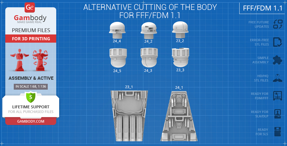
FFF/FDM 1.1 version features:
- Contains 62 parts;
- A printed model is 533 mm tall, 266 mm wide, 603 mm deep;
- Assembly kit includes one lock 62_Ge_lock_10H_x43_FDM to connect parts securely without glue that needs to be printed 43 times;
- Made with fully articulated legs, movable anti-ship laser cannons and opening cockpit;
- The command viewport is separated to be printed with transparent filament;
- Tunnels throughout the walker's body are provided for LED wiring;
- All parts are divided in such a way that you will print them with the smallest number of support structures.
DLP/SLA/SLS 1.1 version features:
- Contains 25 parts;
- A printed model is 266 mm tall, 133 mm wide, 301 mm deep;
- Made with fully articulated legs and opening cockpit;
- The command viewport is separated to be printed with transparent filament;
- Tunnels throughout the walker's body are provided for LED wiring;
- All parts are divided in such a way to fit the build plates and to ensure that support structures are generated where needed.
FFF/FDM 1.0 version features:
- Contains 62 parts;
- A printed model is 416 mm tall, 183 mm wide, 367 mm deep;
- The initial version of the model saved in 1:100 scale.
DLP/SLA/SLS 1.0 version features:
- Contains 25 parts;
- A printed model is 208 mm tall, 92 mm wide, 184 mm deep;
- The initial version of the model saved in 1:200 scale.
WHAT WILL YOU GET AFTER PURCHASE?
- STL files of AT-M6 Walker Model for 3D printing which consist of 87 parts;
- 4 versions of files for this model for FFF/FDM and DLP/SLA printers;
- High-poly detailed model of AT-M6 Walker;
- Detailed settings that we provide as a recommendation for Cura , Simplify3D and Slic3r for the best print;
- Full technical support from the Gambody Support Team.
You can get the model of AT-M6 Walker for 3D Printing immediately after the purchase! Just click the green Buy button in the top-right corner of the model’s page. You can pay with PayPal or your credit card.
Watch the tutorial on how to assemble AT-M6 Walker 3D Printing Model at Gambody YouTube channel.
Also, you may like the other Walker 3D Printing Models as well as other Star Wars 3D Printing Models.
_______
FAQ:
Where can I print a model if I have no printer?
How to get started with 3D printing?
How to set up my 3D printer?
How to choose right 3D model print bed positioning?
How to paint printed figurine?
This model was tested in Cura 3.4.1 and printed on an Ultimaker 2 in PLA material. Below you can find printing recommendations for Cura, Simplify3D and Slic3r softwares.
Recommendations: For all parts of Locks you need to change "Brim" type to "Skirt" in Build Plate Adhesion section.
To avoid printing problems, we recommend the following settings:
Quality
Layer Height: 0.1 mm
Initial Layer Height: 0.3 mm
Line Width: 0.4 mm
Wall Line Width: 0.4 mm
Outer Wall Line Width: 0.4 mm
Inner Wall(s) Line Width: 0.4 mm
Top/Bottom Line Width: 0.4 mm
Infill Line Width: 0.4 mm
Skirt/Brim Line Width: 0.4 mm
Support Line Width: 0.4 mm
Initial Layer Line Width: 100%
Shell
Wall Thickness: 0.8 mm
Wall Line Count: 2
Outer Wall Wipe Distance: 0.2 mm
Top Surface Skin Layers: 0
Top/Bottom Thickness: 0.8 mm
Top Thickness: 0.8 mm
Top Layers: 8
Bottom Thickness: 0.8 mm
Bottom Layers: 8
Top/Bottom Pattern: Lines
Bottom Pattern Initial Layer: Lines
Top/Bottom Line Directions: [ ]
Outer Wall Inset: 0 mm
Compensate Wall Overlaps: Check
Compensate Outer Wall Overlaps: Check
Compensate Inner Wall Overlaps: Check
Fill Gaps Between Walls: Everywhere
Filter Out Tiny Gaps: Check
Horizontal Expansion: 0 mm
Initial Layer Horizontal Expansion: 0 mm
Z Seam Alignment: Sharpest Corner
Seam Corner Preference: Hide Seam
Ignore Small Z Gaps: Check
Extra Skin Wall Count: 1
Infill
Infill Density: 20%
Infill Line Distance: 4.0 mm
Infill Pattern: Grid
Infill Line Directions: [ ]
Infill X Offset: 0 mm
Infill Y Offset: 0 mm
Infill Overlap Percentage: 10%
Infill Overlap: 0.04 mm
Skin Overlap Percentage: 5%
Skin Overlap: 0.02 mm
Infill Wipe Distance: 0.1 mm
Infill Layer Thickness: 0.1 mm
Gradual Infill Steps: 1
Gradual Infill Steps Height: 1.5 mm
Infill Before Walls: Check
Minimum Infill Area: 0 mm2
Skin Removal Width: 0.8 mm
Top Skin Removal Width: 0.8 mm
Bottom Skin Removal Width: 0.8 mm
Skin Expand Distance: 0.8
Top Skin Expand Distance: 0.8
Bottom Skin Expand Distance: 0.8
Maximum Skin Angle for Expansion: 90˚
Minimum Skin Width for Expansion: 0.0
Material
Initial Layer Flow: 100%
Enable Retraction: Check
Retraction Extra Prime Amount: 0 mm3
Retraction Minimum Travel: 0.8 mm
Maximum Retraction Count: 90
Minimum Extrusion Distance Window: 6.5 mm
Nozzle Switch Retraction Distance: 16 mm
Nozzle Switch Retraction Speed: 20 mm/s
Nozzle Switch Retract Speed: 20 mm/s
Nozzle Switch Prime Speed: 20 mm/s
Speed
Print Speed: 45 mm/s
Infill Speed: 45 mm/s
Wall Speed: 22.5 mm/s
Outer Wall Speed: 22.5 mm/s
Inner Wall Speed: 45 mm/s
Top/Bottom Speed: 15 mm/s
Travel Speed: 45 mm/s
Initial Layer Speed: 22.5 mm/s
Initial Layer Print Speed: 22.5 mm/s
Initial Layer Travel Speed: 30 mm/s
Skirt/Brim Speed: 30 mm/s
Maximum Z Speed: 0 mm/s
Number of Slower Layers: 2
Travel
Combing Mode: All
Avoid Printed Parts when Traveling: Check
Travel Avoid Distance: 0.625 mm
Layer Start X: 0.0 mm
Layer Start Y: 0.0 mm
Cooling
Enable Print Cooling: Check
Fan Speed: 100%
Regular Fan Speed: 100%
Maximum Fan Speed: 100%
Regular/Maximum Fan Speed Threshold: 10 s
Initial Fan Speed: 0%
Regular Fan Speed at Height: 0.3 mm
Regular Fan Speed at Layer: 2
Minimum Layer Time: 5 s
Minimum Speed: 10 mm/s
Support
Generate Support: Check
Support Placement: Everywhere
Support Overhang Angle: 50°
Support Pattern: Zig Zag
Connect Support ZigZags: Check
Support Density: 15 %
Support Line Distance: 3 mm
Support Z Distance: 0.1 mm
Support Top Distance: 0.1 mm
Support Bottom Distance: 0.1 mm
Support X/Y Distance: 1 mm
Support Distance Priority: Z overrides X/Y
Minimum Support X/Y Distance: 0.25 mm
Support Stair Step Height: 0.3 mm
Support Stair Step Maximum Width: 5.0 mm
Support Join Distance: 2.0 mm
Support Horizontal Expansion: 0.2 mm
Support Infill Layer Thickness: 0.1 mm
Gradual Support Infill Steps: 0
Use Towers: Check
Tower Diameter: 3.0 mm
Minimum Diameter: 3.0 mm
Tower Roof Angle: 65°
Build Plate Adhesion
Build Plate Adhesion Type: Brim (for all parts of locks use "Skirt")
Skirt/Brim Minimum Length: 250 mm
Brim Width: 8.0 mm
Brim Line Count: 18
Brim Only on Outside: Check
Mesh Fixes
Union Overlapping Volumes: Check
Merged Meshes Overlap: 0.15 mm
Special Modes
Print Sequence: All at Once
Surface Mode: Normal
Experimental
Slicing Tolerance: Middle
Maximum Resolution: 0.01 mm
Flow rate compensation max extrusion offset: 0 mm
Flow rate compensation factor: 100%
Disclaimer: This model will look outstanding if printed on SLA/SLS 3D printer. The accuracy of the model printed on FFF printer can vary from the result shown in the pictures.
This model was tested with PLA material.
To avoid printing problems, we recommend the following settings:
Extruder
Nozzle Diameter: 0.4 mm
Extrusion Multiplier: 0.97
Extrusion Width: Auto
Retraction Distance: 5.00 mm
Extra Restart Distance: 0.00 mm
Retraction Vertical Lift: 0.08 mm
Retraction Speed: 5400.0 mm/min
Wipe Distance: 5.00 mm
Layer
Primary Layer Height: 0.2 mm
Top Solid Layers: 8
Bottom Solid Layers: 5
Outline/Perimeter Shells: 2
Outline Direction: Inside-Out
First Layer Height: 90%
First Layer Width: 100%
First Layer Speed: 20%
Additions
Use Skirt/Brim: Check
Skirt Layers: 1
Skirt Offset from Part: 6.00 mm
Skirt Outlines: 5
Infill
Internal Fill Pattern: Fast Honeycomb
External Fill Patern: Rectilinear
Interior Fill Percentage: 10%
Outline Overlap: 22%
Infill Extrusion Width: 100%
Minimum Infill Length: 5.00 mm
Combine Infill Every: 1 layers
External Infill Angle Offsets: 45/-45 deg
Support
Generate Support Material: Check
Support Infill Percentage: 15%
Extra Inflation Distance: 1.00 mm
Support Base Layers: 0
Combine Support Every: 1 layers
Dense Support Layers: 0
Dense Infill Percentage: 70%
Support Type: Normal
Support Pillar Resolution: 5.00 mm
Max Overhang Angle: 60 deg
Horizontal Offset From Part: 0.50 mm
Upper Vertical Separation Layers: 1
Lower Vertical Separation Layers: 1
Support Infill Angles: 45 deg
Temperature
Extruder 1 Temperature: 210
Heated Bed: 60
Cooling
Increase fan speed for layers below: 45.0 sec
Maximum Cooling fan speed: 50%
Bridging fan speed override: 100%
Speeds
Default Printing Speed: 4800.0 mm/min
Outline Underspeed: 50%
Solid Infill Underspeed: 80%
Support Structure Underspeed: 80%
X/Y Axis Movement Speed: 10800.0 mm/min
Z Axis Movemen Speed: 1002.0 mm/min
Adjust printing speed for layers below: 15.0 sec
Allow speed reduction down to: 20%
Other
Unsupported area threshold: 20.0 sq m
Layer height
Layer height: 0.1 mm
First layer height: 90%
Vertical shells
Perimeters: 2
Horizontal shells
Soid layers:
Top: 8
Bottom: 5
Quality
Detect thin walls: Check
Detect bridging perimeters: Check
Advanced
Seam position: Random
Infill
Fill desity: 20%
Fill pattern: Honeycomb
Top/bottom fill pattern: Rectilinear
Reducing printing time
Combine infill every: 1 layers
Advanced
Solid infill every: 0 layers
Fill angle: 25 deg
Solid infill threshold area: 0mm
Skirt
Loops: 2
Distance from object: 6 mm
Skirt height: 1 layers
Minimum extrusion length: 4 mm
Brim
Brim width: 10 mm
Support material
Generate support material: Check
Overhang threshold: 45 deg
Enforce support for the first: 3 layers
Raft
Raft layers: 0 layers
Options for support material and raft
Contact Z distance: 0.1 mm
Pattern: Rectilinear
Patter spacing: 2 mm
Pattern angle: 0 deg
Interface layers: 2 layers
Interface pattern spacing: 0.2 mm
Speed for print moves
Perimeters: 60 mm/s
Small perimeters: 20 mm/s
External perimeters: 20 mm/s
Infill: 60 mm/s
Solid infill: 60 mm/s
Top solid infill: 30 mm/s
Support material: 50 mm/s
Support material interface: 100%
Bridges: 30 mm/s
Gap fill: 50 mm/s
Speed for non-print moves
Travel: 60 mm/s
Modifiers
First layer speed: 30 mm/s
Acceleration control
Perimeters: 800 mm/s
Infill: 1500 mm/s
Bridge: 1000 mm/s
First layer: 1000 mm/s
Default: 1000 mm/s
Autospeed
Max print speed: 100 mm/s
Max volumetrix speed: 0 mm/s
Extrusion width
Default extrusion width: 0.42 mm
First layer: 0.42 mm
Perimeters: 0.42 mm
External perimeters: 0.42 mm
Infill: 0.42 mm
Solid infill: 0.42 mm
Top solid infill: 0.42 mm
Support material: 0.42 mm
Overlap
Infill/Perimeters overlap: 20%
Flow
Bridge flow ratio: 0.95
Other
XY Size Compensation: 0 mm
Threds: 8
Resolution: 0 mm
You are about to report AT-M6 Walker 3D Printing Model | Assembly for violating our Terms and Conditions. Please take a few moments to fill in the following information.


Comments
comments powered by Disqus